3D model
To aid in the design of all the parts, I created a 3D model of everything using OpenSCAD. Below is a screen shot showing a typical view:
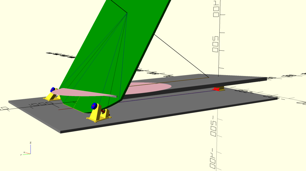
Here, the circle bearing is shown as green (this has been extended upward in the view, however only the part below the top plate will be constructed). The south bearing is shown as two pieces, barely visible on the right. The north bearings are shown in yellow, and will contain two bearings and a shaft. The pink circle on the top plate represents the round base of the telescope. Yes, part of the base sticks past the end of the top plate, but all 3 legs of the base are firmly supported so this is not an issue.
The OpenSCAD model was very valuable in the overall design. I am able to enter a rotation angle, to simulate any angle along the full 15 degrees of rotation. I was able to play around with the height of the south bearing, the distance between the table and the ground board, and more. The positioning and height of the north bearings were quite important, in order allow a +- 7.5 degree rotation from the midpoint. I also wanted to minimize the distance between the table and the ground board. I ended up with a design where the circular bearing passes through a slot on the ground board (this is OK since the ground board is supported on rubber feet, so there is clearance and of course the circular bearing does not touch the ground.)
North Bearings
Many of the parts were 3D printed using PLA, and the OpenSCAD model was used to create these parts: south bearing (two parts), north bearings (x2), motor mount, pads for telescope base feet, and box housing the electronics to drive the motor.
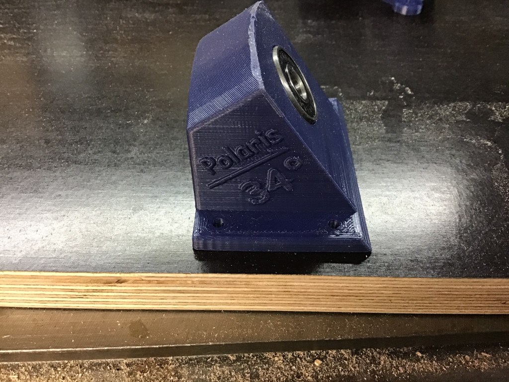
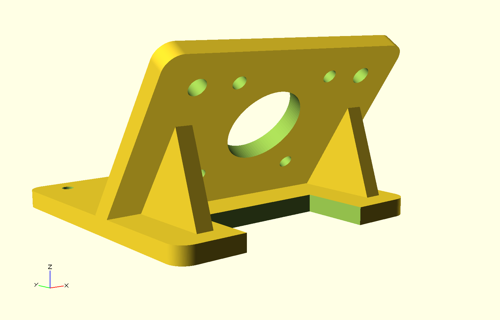
Below is one of the north bearings.
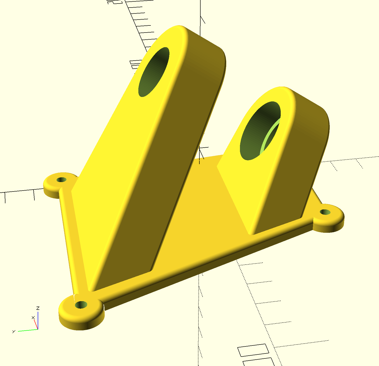
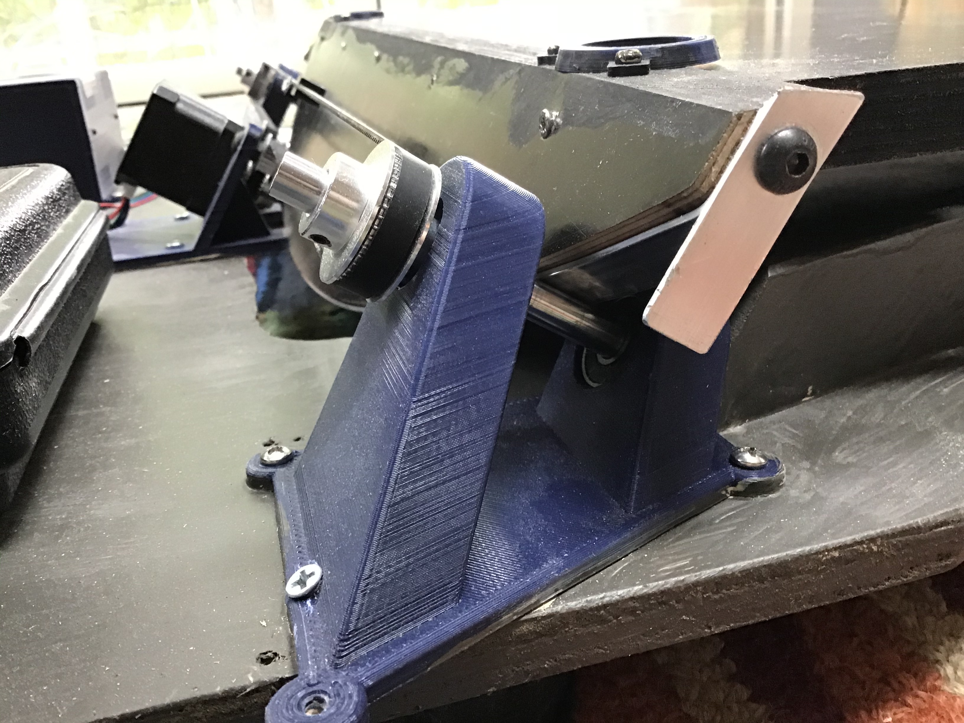
On the left is the rendering from OpenSCAD, and on the right, a photo of the finish part. The part was printed in PLA and is surprisingly strong.
This design would be very complicated to fabricate from wood or metal, and that’s a real advantage of using a 3D printer for this design.
Standard skateboard bearings are inserted into the two openings. These have a 22 mm overall diameter, with an 8mm hole and 7 mm thick. An 8 mm rod goes through both bearings, and a drive gear is attached on one end which uses a standard toothed belt. This design borrows heavily from my experience building 3D printers.
The circle section was cut from 3/4″ plywood, and a 1/16″ aluminum bar was bent around it in order to provide a strong bearing surface. The bearing was adjusted so that the bar perfectly matches up with this aluminum bearing surface, and makes contact across the whole surface.
South Bearing
This bearing takes a lot of weight and is probably the weak point of the design. Still, I haven’t seen any evidence of problems with it.
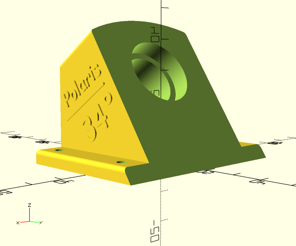
This is not much more than a chunky block of material with a hole for the bearing and an angled face. For style points I added the text about pointing to Polaris, but unfortunately you can’t see it on the finished product. :>(
There is another part that is almost exactly the same which is turned upside down and is mounted on the bottom of the plate. This part does not have a bearing, however, it just has an 8 mm hole to accept a short segment of rod. A bearing washer is used between the two parts. You might think this would mean the plate could be easily removed from the base, but you’d be wrong. It’s a tight fit, it was tricky to assemble everything, and they don’t easily come apart.
Plate
The plate was cut from 3/4″ baltic birch with a phenolic coating. The shape was made rounded, for no other reason than it looked interesting.
The circle section bearing was also cut from the same material, and then attached to the front of the plate using construction screws. I discovered wood glue does not work on phenolic coating!
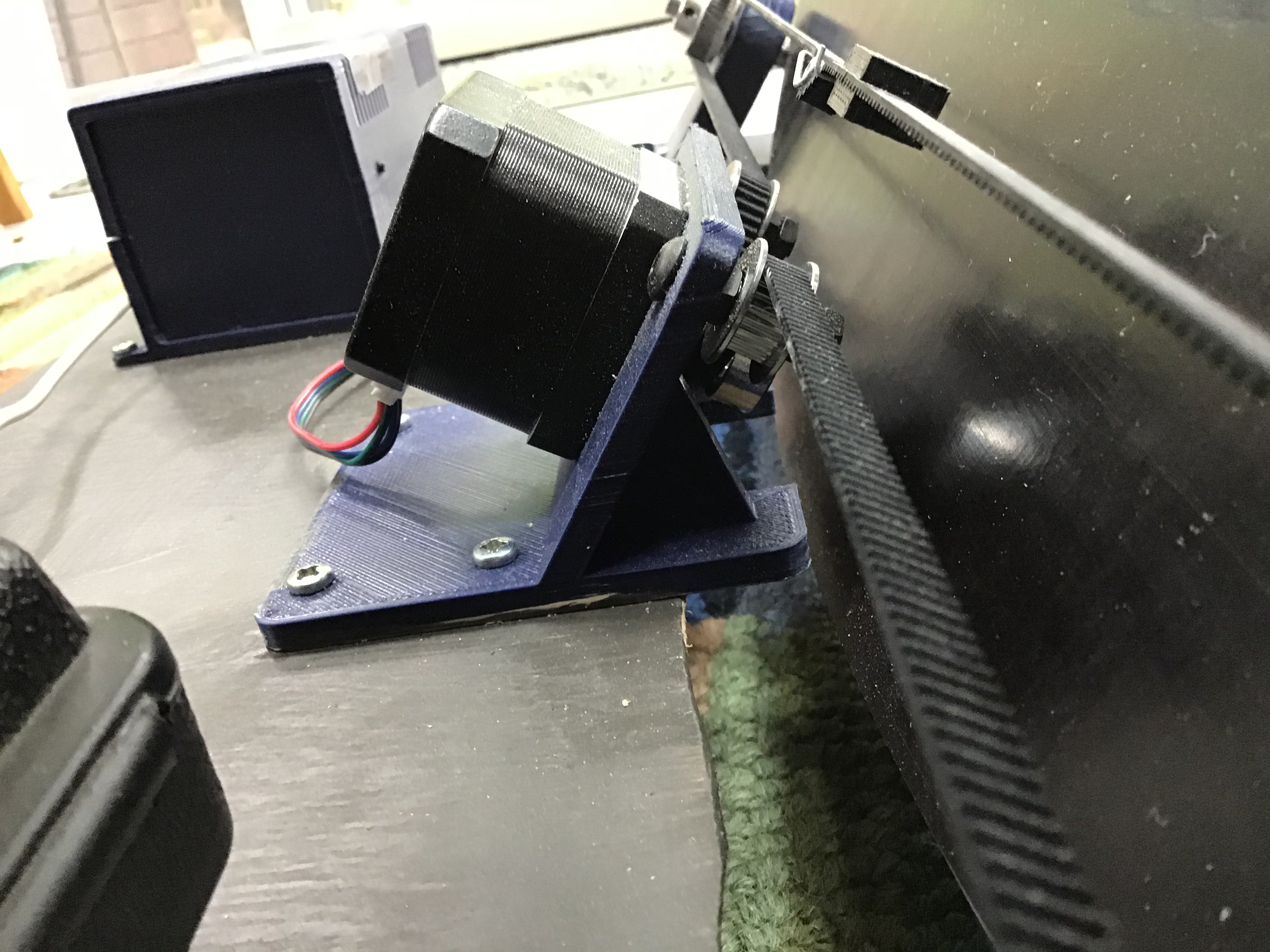
Drive Motor Mount
A stepper motor drives everything via a toothed belt. The motor is mounted at the same angle as the 8 mm rods (alpha) and the belt goes over two idler bearings on either side of the motor. The belt is joined in a loop using a 3D printed part (something left over from our last 3D printer build), with a tensioner. This arrangement worked well because the belt doesn’t need to make a full loop.
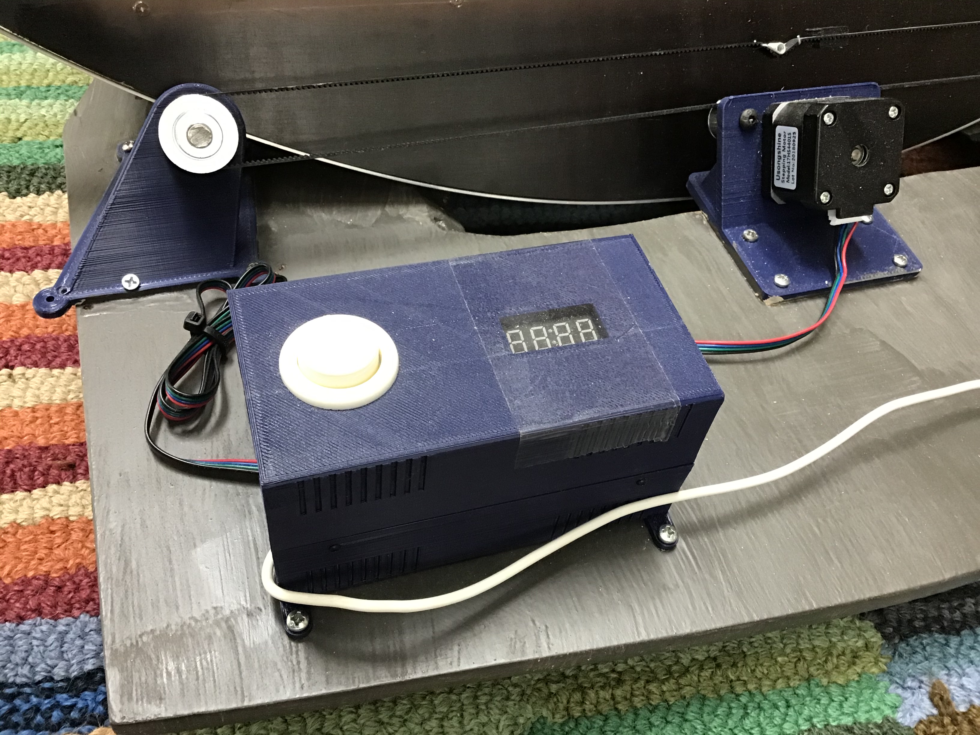
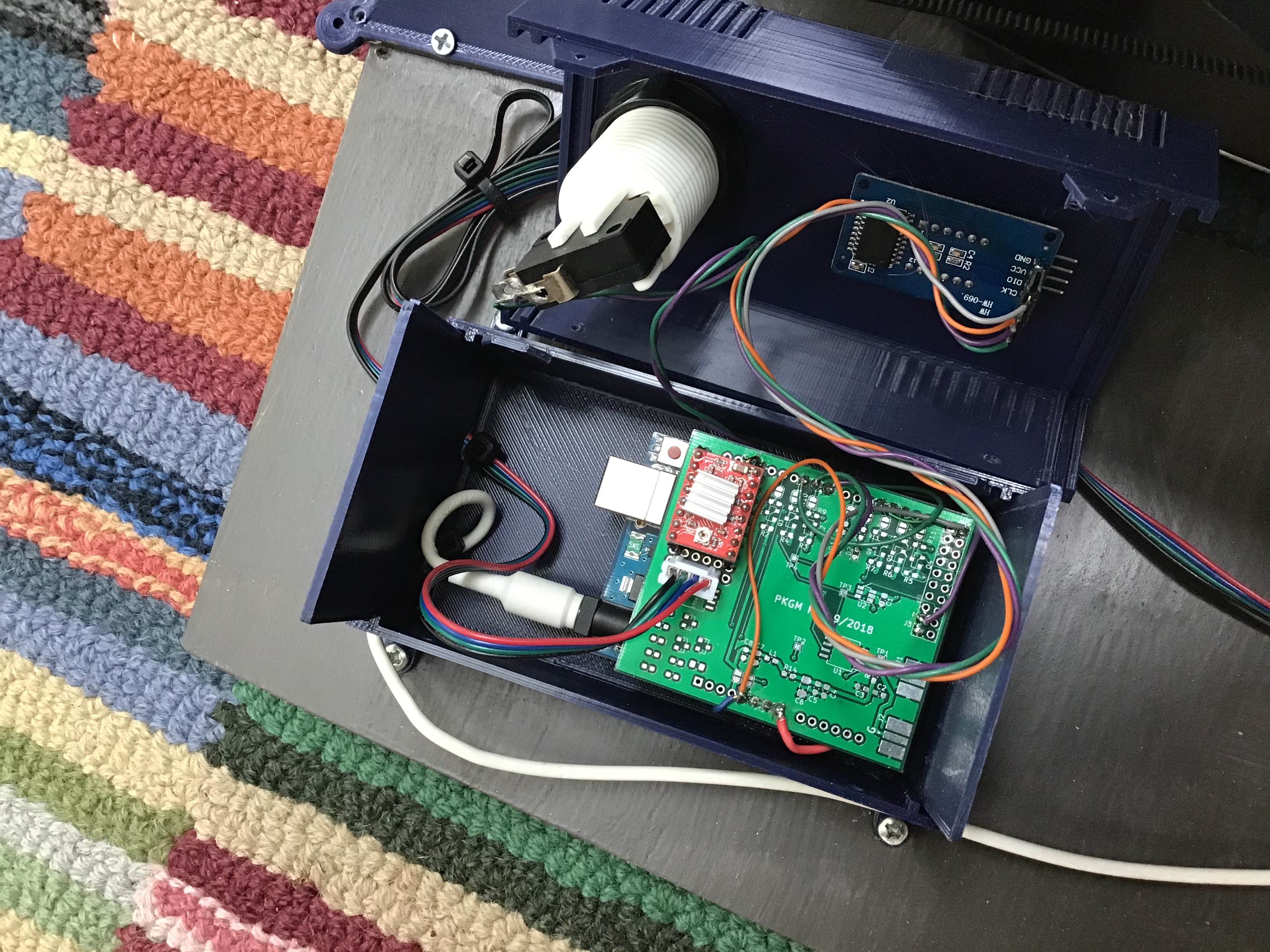
Motor Controller
I used an Arduino with external stepper motor driver and a 4 digit 7-segment display. The white button controls the modes, cycling between motor off, motor hold, and motor drive. There’s a special mode: if you power-on the unit with the white button pressed, it enters a test mode where time is sped up by a factor of 60 – i.e. minutes become seconds – which makes testing a lot easier.
The software can be found here.
Calculating the motor speed was interesting. Below is an excerpt from the software explaining it all
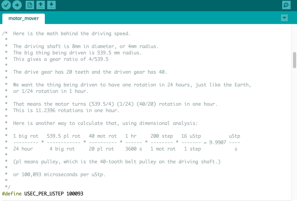
Now let’s see how it turned out.

What’s the size of the motor you used? I would want to do something similar with the timing belt because VNS is a bit hard for me to get the grasp of, but I have a bigger scope (about 35kg total weight) and live at a higher latitude (45°), so I’d need to have a motor at least 61% “stronger” than the one you used, from my calculations
LikeLike
It’s a NEMA 17 motor like this:
Usongshine Nema 17 Stepper Motor 42BYGH 1.8 Degree 38MM 1.5A 42 Motor (17HS4401S) 42N.cm (60oz.in) 4-Lead with 1m Cable and Connector for DIY CNC 3D Printer https://a.co/d/3diAidx
Best of luck to you!
LikeLike