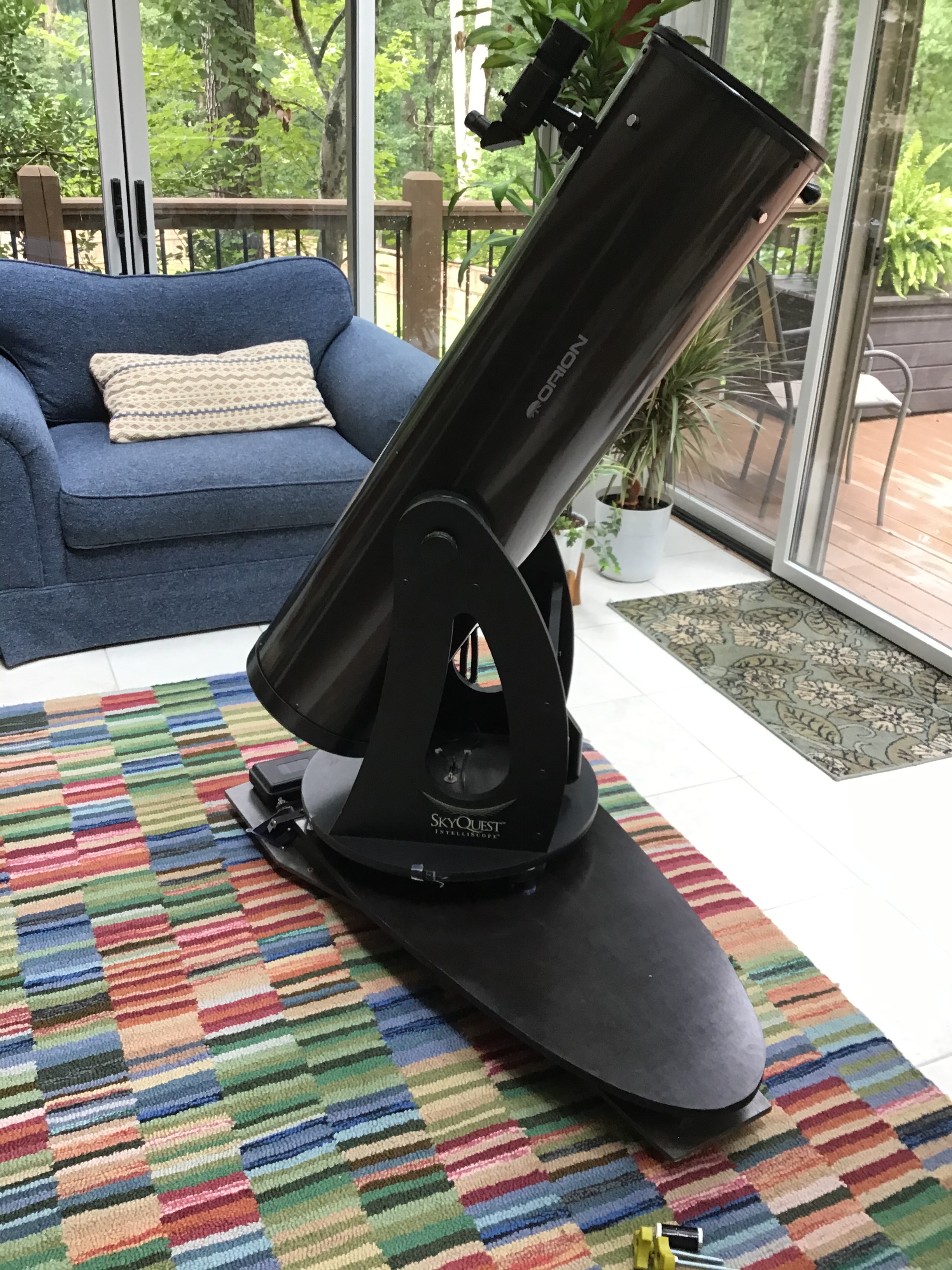
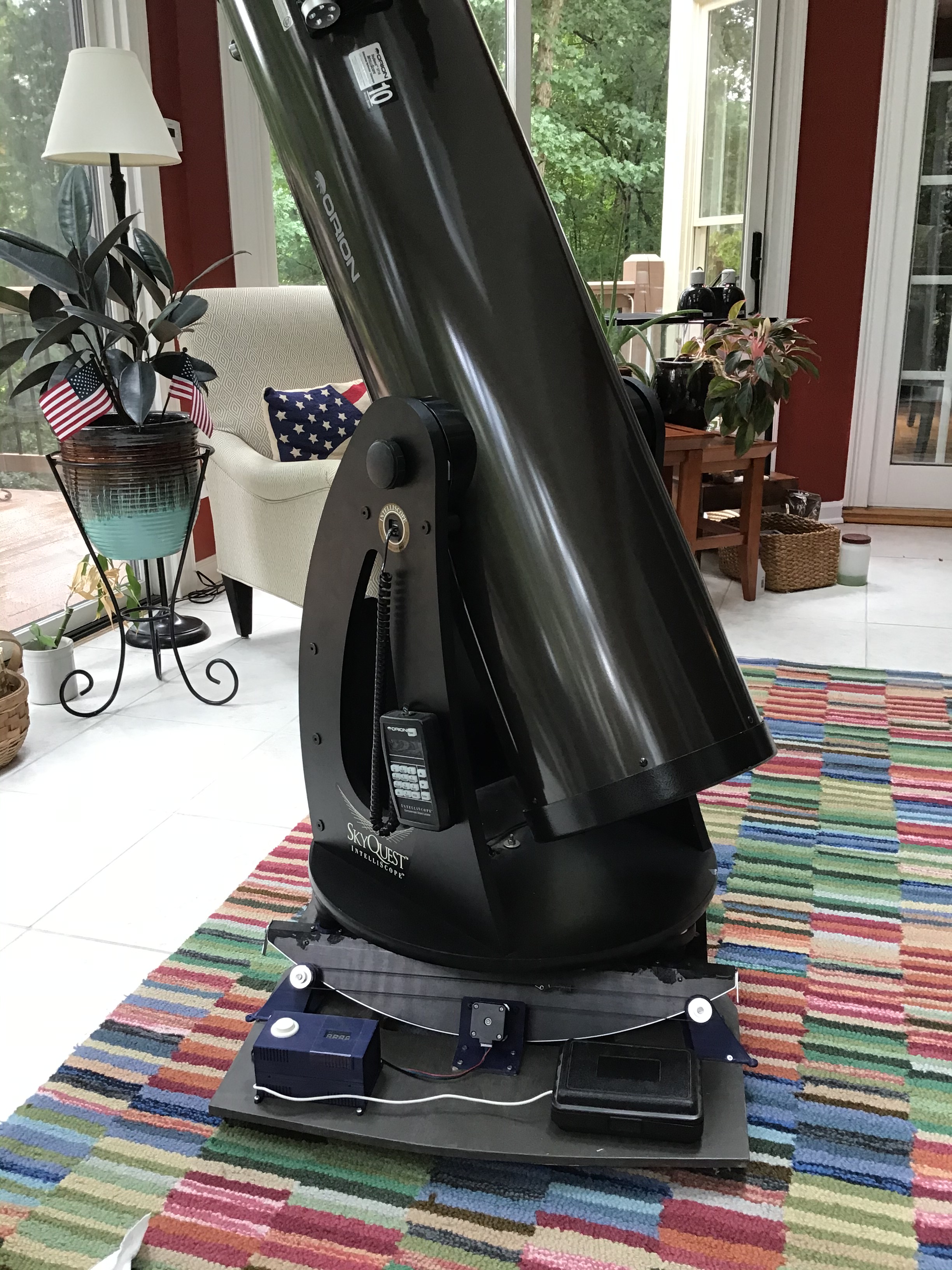
Here’s the finished product!
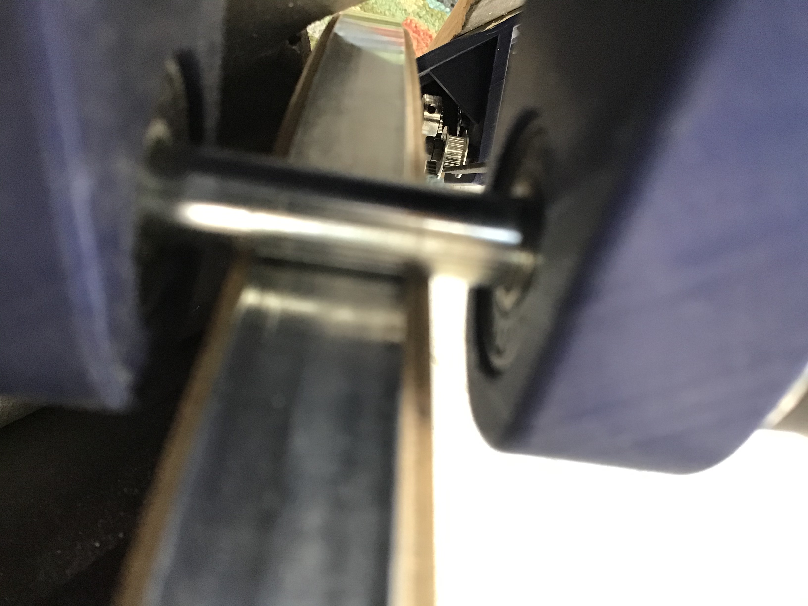
It looks great, and works well too. The stepper motor makes a clicking or tapping sound, about 10 times per second, which is a little distracting but not bad.
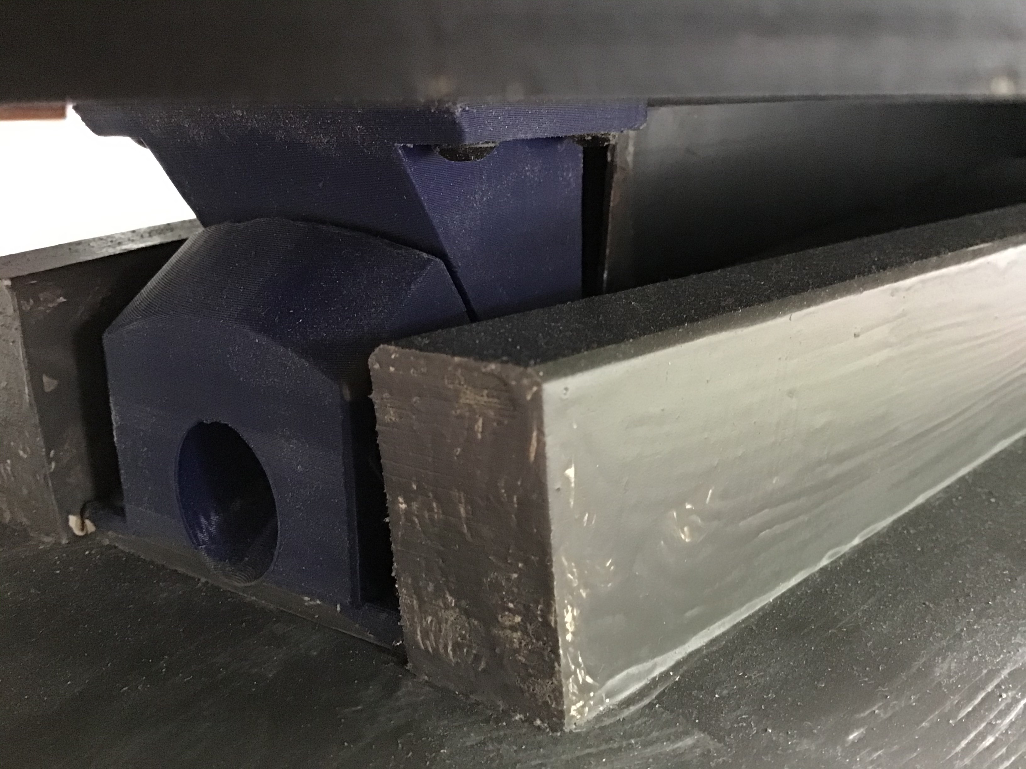
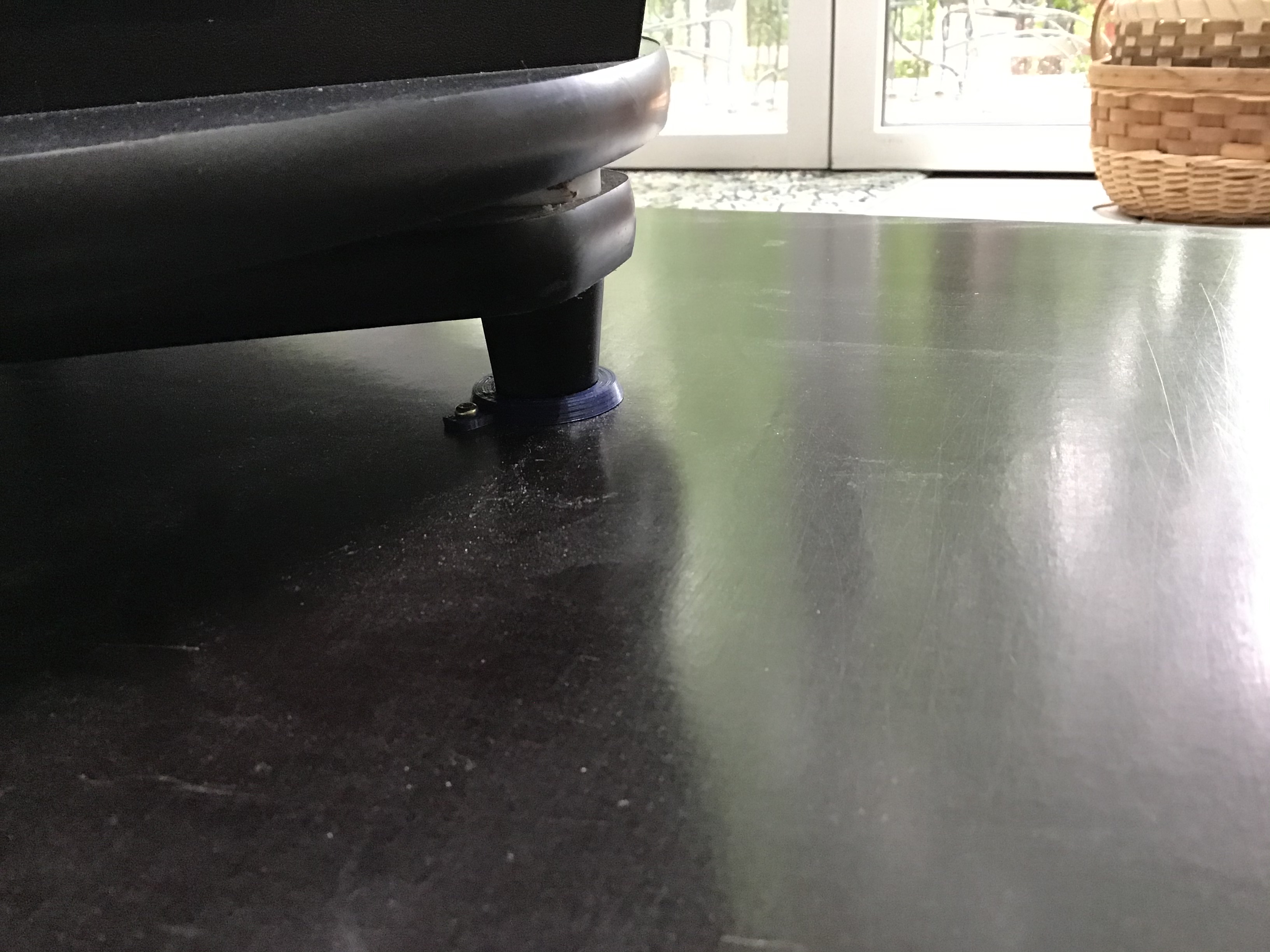
The base board (1/2″ plywood) was reinforced with two 1x2s, and has three thick rubber feet. The plate was reinforced with a rectangular hollow steel bar. Overall the platform is quite strong. Also heavy, but I have an arrangement to lock everything in place for storage, and there’s a carrying handle too.
The feet of the telescope base fit into three 3D printed rings. This means the scope is always positioned in exactly the right place.
A few more shots:

Great stuff Howard. Good to be back in school with an excellent teacher!
LikeLike
Glad you enjoyed it
LikeLike
Hello Howard,
Thank you for sharing your design. I ran across this on Thingiverse in August and I’m finally getting around to designing one for my own 10″ dob. Lots of inspiration here.
May I ask if you’ve ever had issues with the aluminum plate slipping on the 8mm steel rollers, rather than tracking accurately? I’m tempted to affix a toothed belt to the underside of the bearing and drive it directly from a gear on a stepper motor, but your approach is much more clean. I’d rather emulate you than go the other route!
Thank you.
LikeLike
Hi Jesse – glad to hear you are building a platform.
So far there has been no evidence of slipping between the steel rollers and the aluminum. But I agree it’s a concern. That’s why I decided to drive both rollers, instead of just one, to minimize the risk.
If slipping did happen, my plan was to roughen up the aluminum somehow (not sure if that would have helped or not…).
Here’s more info: with the motor locked, I can reposition the platform/scope by hand which means the aluminum is sliding on the roller. This takes some effort – i.e. you can feel there’s a decent amount of resistance as the aluminum slides on the rods. So that’s evidence that there is a decent amount of friction between the two.
Putting the scope’s center of gravity along the Polaris axis really helps here. If slipping did occur, maybe that’s another thing I could do – try to fine tune this balance.
Your idea of the toothed belt seems like it would work fine. It makes the drive mechanism simpler. You’d need a way to make sure the motor/gear is pushed up against the underside of the bearing, but that seems doable.
The best of luck to you in your building, and sky-watching!
Regards,
Howard
LikeLike
I was inspired by your project until I bought a 3D printer, I wanted to adjust the angle at the North and South Poles but I don’t know what, I need 48. I’m a beginner in modeling. don’t know any instructions on how to edit it? beautiful project congratulations
LikeLike
Thank you for your note, I appreciate it! To address your question, a platform designed for 48 degrees N would be quite different from this. The Gee type design would not be the best, I think. I recommend you visit this page http://www.reinervogel.net/index_e.html?/Plattform/Plattform_e.html which describes various configurations. I found it amazing and informative to look at the different builds people have done. That’s how I got started with mine.
LikeLike